

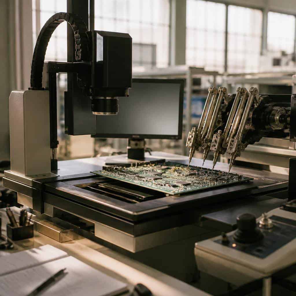
Getting started with printed circuit board (PCB) testing can feel like stepping into a complex world. The good news is it doesn’t have to be overwhelming. The core of PCB testing lies in verifying the functionality and integrity of the circuits before they move to the next production stage or into customer hands. Understanding the types of test equipment available and what to consider when selecting them can make this process much smoother.
Types of PCB Testing Equipment
In-Circuit Testers (ICT)
In-Circuit Testers are widely used for checking individual components and solder joints on a populated PCB. They apply electrical probes to test nets and verify that resistors, capacitors, and other components have the expected values and orientations. This type of test equipment helps identify manufacturing faults early, making it essential for quality control in production lines.
Flying Probe Testers
Unlike fixed ICT fixtures, flying probe testers use moving probes to test circuits. This flexibility allows for testing smaller batches or prototypes without the cost of custom fixtures. They work well for complex boards and provide detailed fault diagnostics, although the test time may be longer compared to ICT.
Functional Test Systems
Functional testers evaluate the PCB as a whole, simulating its working environment and operation. This method confirms that the assembled board performs according to design specifications by running software or electrical stimuli and monitoring outputs. Functional testing is critical for catching system-level issues that in-circuit tests might miss.
Automated Optical Inspection (AOI)
AOI equipment uses cameras and image processing to check for visual defects such as missing components, solder bridges, or misalignments. Though not strictly electrical testing, it plays a vital role in early defect detection before electrical tests commence.
Key Criteria for Selecting PCB Test Equipment
- Board Complexity and Volume: For high-volume production of relatively simple boards, ICT fixtures provide speed and reliability. For low volumes or prototypes, flying probe is more cost-effective.
- Test Coverage Requirements: Consider whether you need component-level checks, full assembly testing, or functional validation.
- Budget and Setup Time: ICT requires upfront fixture costs and longer setup, while flying probe and AOI systems offer quicker implementation with less tooling.
- Accuracy and Diagnostic Detail: Some testers provide detailed fault localization and measurement precision important for troubleshooting early failures.
Practical Steps to Implement PCB Testing
Starting a PCB test program involves several practical steps. First, define the test objectives clearly—what defects or faults you want to detect and at which production stages. Next, select the test methods and equipment that align with your board design and production scale.
Develop test programs or scripts tailored to the specific board variants. This often requires collaboration between design and test engineers to ensure coverage of critical nets and components. Once the equipment and programs are ready, initial pilot runs with known good and faulty boards help validate the test setup.
Ongoing monitoring of test results will highlight process trends or recurring defects, guiding continuous process improvements.
Understanding PCB Test Standards and Cleanliness
Testing a PCB’s electrical integrity is only part of the quality check. Cleanliness, particularly ionic contamination, can affect long-term reliability. Standards such as those from IPC define limits and test methods to evaluate PCB cleanliness.
Advanced analytical methods like ion chromatography help detect and quantify ionic residues on board surfaces and assemblies. Integrating cleanliness testing into your quality routine ensures that potential corrosion or electrical leakage problems are minimized before final product shipment.
For more detailed insight into these standards and testing technologies, the resource on pcb test procedures covers key aspects that complement electrical testing efforts.
| Test Equipment Type | Main Purpose | Best Use Scenario | Setup Complexity |
|---|---|---|---|
| In-Circuit Tester | Component and solder joint verification | High-volume production | High (fixture design and manufacturing) |
| Flying Probe Tester | Flexible electrical testing without fixtures | Prototyping and low volume | Low to moderate |
| Functional Test System | System-level operation validation | Complex assemblies requiring end-use simulation | Moderate to high |
| Automated Optical Inspection | Visual defect detection | Early stage defect screening | Low to moderate |
Being equipped with the right knowledge and tools for PCB testing is fundamental to maintaining product quality and reliability. By understanding test equipment types, selection factors, and incorporating cleanliness considerations, the PCB production process becomes more controlled and predictable. This foundation helps manufacturers confidently deliver boards that meet performance and durability expectations.